Introduction
A direct shear test is a laboratory or field test used by geotechnical engineers to measure the shear strength properties of soil or rock material, or of discontinuities in soil or rock masses.
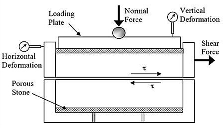
The concept of direct shear is simple and mostly recommended for granular soils, sometimes on soils containing some cohesive soil content. The cohesive soils have issues regarding controlling the strain rates to drained or undrained loading. In granular soils, loading can always assumed to be drained. A schematic diagram of shear box shows that soil sample is placed in a square box which is split into upper and lower halves. Lower section is fixed and upper section is pushed or pulled horizontally relative to other section; thus forcing the soil sample to shear/fail along the horizontal plane separating two halves. Under a specific Normal force, the Shear force is increased from zero until the sample is fully sheared. The relationship of Normal stress and Shear stress at failure gives the failure envelope of the soil and provide the shear strength parameters (cohesion and internal friction angle).
Objective(s) of the Experiment
This test method covers the determination of the shear strength of a soil material in direct shear.
Equipments and Materials Needed
- Direct shear box apparatus, and Loading frame (motor attached).
- Dial gauge, Proving ring, Balance to weigh up to 200 g.
- Tamper, Straight edge, Aluminum container, Spatula.
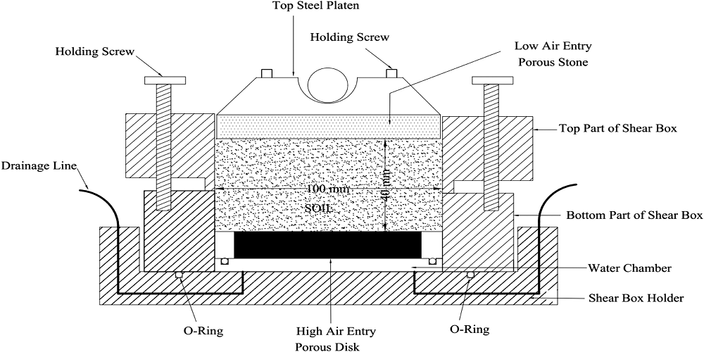
A shear box is either circular or square, made of stainless steel, bronze, or aluminum, with provisions for drainage through the top and bottom. The box is divided vertically by a horizontal plane into two halves of equal thickness which are fitted together with alignment screws. The shear box is also fitted with gap screws, which control the space (gap) between the top and bottom halves of the shear box. The soil specimen is placed in the shear box.
The soil specimens may be square or circular in plan. The size of the specimens generally used is about 51 mm x 51 mm or 102 mm x 102 mm across and about 25 mm high. The box is split horizontally into halves. Normal force on the specimen is applied from the top of the shear box. The normal stress on the specimens can be as great as 1050kN/m2. Shear force is applied by moving one-half of the box relative to the other to cause failure in the soil specimen.
A proving ring is used to indicate the shear load taken by the soil initiated in the shearing plane.
Procedures
- Check the inner dimension of the soil container, and put the parts of the soil container together.
- Calculate the volume of the container. Weigh the container.
- Place the soil in smooth layers (approximately 10 mm thick). If a dense sample is desired tamp the soil.
- Weigh the soil container, and find the weight of soil. Calculate the density of soil.
- Plane the top surface of soil, and put the upper grating stone and loading block on top of soil.
- Measure the thickness of soil specimen.
- Apply the desired normal load and Remove the shear pin.
- Attach the dial gauge which measures the change of volume.
- Record the initial reading of the dial gauge and calibration values.
- Check all adjustments to see that there is no connection between two parts except sand/soil.
- Start the motor. Take the reading of the shear force and volume change till failure.
- Add corresponding normal stress and continue the experiment till failure
- Record carefully all the readings. Set the dial gauges zero, before starting the experiment
Results and Calculations
- Shear stress (τ) on the horizontal failure plane are calculated as τ = S/A; Where S is shear force. A is the cross sectional area of the sample, which decreases slightly with the horizontal deformations.
- Corrected area (Acorr) needs to be calculated for calculating the shear stress at failure.
Acorr = A0 (1-δ),
Where δ is the horizontal displacement due to shear force applied on specimen.
A0 is the initial area of the soil specimen.- Shear Stress = (Proving ring reading x Proving ring constant)/A
- Horizontal displacement = Horizontal dial gauge reading x Least count of horizontal dial gauge
- Vertical displacement = Vertical dial gauge reading x Least count of vertical dial gauge
- Shear stress at failure needs to be calculated for all three tests performed at three different normal stresses to plot the failure envelope.
Data Calculation Sheet for Direct Shear Test
Data Recorded
- Size of the sample = ____________
- Least count of dial gauge (Horizontal) = _______
- Area of the sample (Cross Sectional ) = _______
- Least count of dial gauge (Vertical) = _______
- Volume of the sample = __________
- Proving Ring No. = _______
- Weight of the sample (gm) = _______
- Proving ring constant = _______
- In-situ Density of the sample (gm/cc) = _______
- Normal stress (Kg/ sq.cm) = _______
- In-situ water content (%) = _______
- Normal stress = (Applied Normal Load x Lever Ratio) / Cross sectional Area of sample = _______
- Normal stress =_________
Data Sheet
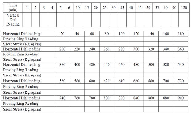
Note: This data sheet is provided for each values of normal stress applied
References
- Indian Institute of Technology, Gandhinagar (2002). ‘Direct Shear Test (IS-2720-PART-13-1986)’. Department of Civil Engineering, Soil Mechanics Laboratory.
- Wikipedia (2018). ‘Direct Shear Test’ https://en.wikipedia.org/wiki/Direct_shear_test. Assessed March 6, 2018.
- Biscontin, G. (2007). ‘CVEN365 Introduction To Geotechnical Engineering Laboratory Manual’. Texas A&M University.
- Das, B.M.and Sobhan, K. (2014). “Principles of Geotechnical Engineering Eighth Edition, SI”


