Introduction
Casting
Casting, also known as foundering, is a manufacturing process in which liquid molten metal is poured into a perforated casting cavity of refractory material (The Mould) made already into the desired shape. The liquid metal is then allowed to solidify; after solidification, the casting metal can be taken out by breaking the mould. For many items, this process can be less expensive than machining the part out of a piece of solid metal.
Terminology Used in Casting Process
Different terminology used in casting process are molding sand, baking sand, facing sand, loam sand, parting sand, CO2 sand, flak, pattern, parting line, sprue, runner, in-gate, riser, chill, and chaplets. As discussed below:
- Molding sand:
Molding sand is the refractory material used for making the mold. It is a mixture of silica, clay, and moisture to get required properties. - Baking sand:
Baking sand consists of refractory material, and it is made of used sand or burnt sand. - Facing sand:
Facing sand is the carbonaceous material sprinkled on the inner surfaces of the molding cavity for obtaining better surface finish. - Loam Sand:
Green or dry sand with at least 50% clay and dries hard is called loam sand. It also contains fire clay. It has 18 to 20% moisture and produces a good surface finish. - Parting sand:
For separating the molds from adhering to each other by separating a fine sharp dry sand called parting sand. It also can be used to keep green sand from sticking to the pattern. It is the clean clay free silica sand. - CO2 sand:
In the sand-in-place of clay sodium silicate (Na2SiO3) is used, called as Carbon dioxide (CO2) sand. When the CO2 is supplied into this sand, it the CO2 will chemically react with sodium. - Flak:
Flak is the molding box used for holding the sand. Based on the situation it can be named as cope, drag, cheek, etc. - Drag:
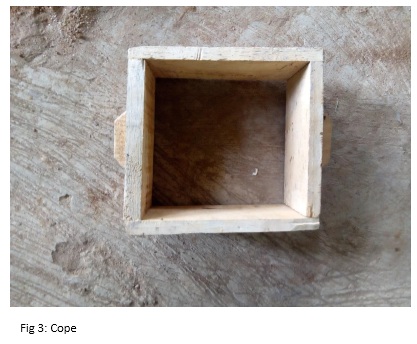
Lower molding flask is called drag. - Cope
Upper molding flask is called cope. - Cheek:
The middle molding flask used in the three-piece pattern is called cheek. - Pattern:
The pattern is the replica of the casting to be produced. - Parting line:
The parting line is the dividing line between the two flasks. - Sprue:
Sprue is the connecting passage between the pouring basin and runner. It controls the flow of molten metal. - Runner:
The runner is the passage used for regulating the flow of molten liquid. - In-gate:
In-gate is the last point of gating from where the molten metal enters the cavity. - Riser:
The riser is the reservoir of molten metal provided in the casting process to compensate the liquid shrinkage’s taking place during solidification. - Chill:
Chill is the metallic piece used for obtaining directional solidification. - Chaplets:
Chaplets are used for supporting the cores inside the mold cavity to take care of its weight and mold cavity to take care of its weight and overcome the buoyancy forces. - Gating
The gating system refers to a series of channels through which molten metal travels from the pouring ladle into the mold cavity, and fills it.
Advantages of Casting Process
- Molten metal flows into small ant section in the molten cavity. Hence any complex shape can be easily produced.
- Practically any material can be casted.
- Ideal method is by producing small quantities
- Due to small cooling rate from all directions, the properties of casting are same in all directions.
- Any size of casting can be produced up to 200 tons.
- Casting is the often cheapest and most direct way of producing a shape with certain desired mechanical properties.
- Certain metals and alloys such as highly creep resistant metal-based alloys for gas turbines cannot be worked mechanically and can be cast only.
- Heavy equipment like machine leads, ship’s propeller, etc. can be thrown easily in the required size rather than fabricating them by joining several small pieces.
- Casting is best suited for composite components requiring different properties in various direction. These are made by incorporating preferable inserts in a casting. For example, aluminum conductors into slots in iron armature for electric motors, wear resistant skins onto shock resistant components.
Limitations of Casting Process
- With normal sand casting process, the dimensional accuracies and surface finish is less.
- Defects are unavoidable.
- Sand casting is labor intensive.
A Mould
A mould is a cavity in a material that receives liquid metal and produces a cooled object in the shape of that cavity. Molds can be simple, such as the forms used to create ingots of metal, like a loaf pan forms bread, but most molds are for more complex shapes. These molds will be made in two parts. A pattern, or what the object is supposed to look like, is imprinted into the mold material. Half of the pattern is imprinted on one side of the mold and half on the other, and the halves are clamped together before the mold is filled. By making the mold in two parts, the pattern can be withdrawn before filling.
In horizontal molding, the top half of the mold is called the cope, and the bottom half is called the drag. In vertical molding, the leading half of the mold is called the swing, and the back half is called the ram.
If a mold is supposed to have internal spaces or holes, a core is often made. These cores are shaped like the internal space. The cores are usually held in place by extending past the casting and being held in place through core prints, which suspends the core like a bridge between two banks. The empty spaces around the core will fill with metal, and the core will be removed from the final casting, leaving a hole where it once was. If the core is very long, it might be supported by chaplets to prop it up. These are usually made of the same metal as the final casting as they sit in the space that will flood with material and become part of the final casting.
One of the important factors in choosing a casting method is dimensional tolerance. Dimensional tolerance is the variation acceptable in the size of the final product. Metal shrinks when cooling, and the type of casting influences the extent. If a product needs to be precise, a client may want a casting method that produces near net casting. This means that the product is very close to being the right size when it is shaken out of the mold.
Another consideration is surface finishing. How granular, bumpy, or rough can the surface of the casting be? What is acceptable for a cast iron pan is not acceptable for a wedding ring. Very smooth metal surfaces are usually created with machining, which is an extra cost: if shiny and smooth is a desired outcome, choosing a casting method with a finer finish may reduce machining costs.
Aluminium
Aluminium or aluminum is a chemical element with symbol Al and atomic number 13. It is a silvery-white, soft, non-magnetic and ductile metal in the boron group. By mass, aluminium makes up about 8% of the Earth’s crust; it is the third most abundant element after oxygen and silicon and the most abundant metal in the crust, though it is less common in the mantle below. The chief ore of aluminium is bauxite. Aluminium metal is so chemically reactive that native specimens are rare and limited to extreme reducing environments. Instead, it is found combined in over 270 different minerals. Aluminium is remarkable for its low density and its ability to resist corrosion through the phenomenon of passivation. Aluminium and its alloys are vital to the aerospace industry and important in transportation and building industries, such as building facades and window frames. The oxides and sulfates are the most useful compounds of aluminium.
Aluminium Casting
Aluminium casting processes are classified as Ingot casting or Mould casting. To manufacturing shaped components, mould casting can be divided into two:
- Sand Casting
- Die Casting
In sand casting, re-usable, permanent patterns are used to make the sand moulds. The preparation and the bonding of this sand mould are the critical step and very often are the rate-controlling step of this process. Two main routes are used for bonding the sand moulds:
- The “green sand” consists of mixtures of sand, clay and moisture.
- The “dry sand” consists of sand and synthetic binders cured thermally or chemically.
The sand cores used for forming the inside shape of hollow parts of the casting are made using dry sand components.
Why Cast Aluminium
It is very strong and durable. It might not be as strong as cast iron, however, it is very close and certainly a type of metal that can be depended on when needed the most. This is one reason that people choose this alloy, but they also like the cost. When compared to other metals, it is very cost effective. It can be purchased at a cost of about half of what you would spend on other types of metals and Al alloy
Fettling
Raw castings often contain irregularities caused by seams and imperfections in the molds, as well as access ports for pouring material into the molds. The process of cutting, grinding, shaving or sanding away these unwanted bits is called “fettling”.
Equipments Needed
- Core Box
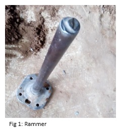
- Rammer
- Sand Muller
- Moulding Flask
- Match-Plate Pattern
- Sprue Cutter
- Moulding Sand
- Riddle Bottom-Board
- Parting Compound
- Strike-Off Bar.
Some diagrams of the apparatus are shown below:
Procedures
- Measure a reasonable quantity of green sand (already mulled and with sufficient green strength).
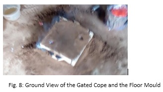
- Making a ground mould (i.e. floor moulding- representing the drag with holes towards the top), place the match plate pattern on top of the moulded green sand on the floor.
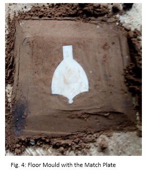
- Afterwards, place the drag on top of the match plate pattern with pins down to align holes and rightly applying dust lightly on the plate pattern to serve as the parting compound.
- Fill the drag riddled with sand; using hammer, ram the riddle sand around the pattern until it develops strength and become rigid within the moulding flask.
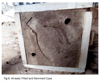
- Add more sand until the drag is filled to overflowing and ram again. And using the strike off bar, remove excess sand level with the top of the drag.
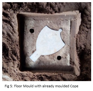
- Having moulded the drag, repeat the same moulding and ramming process for the cope also just above the already moulded drag (floor mould). The cope should be provided for sprue and riser.
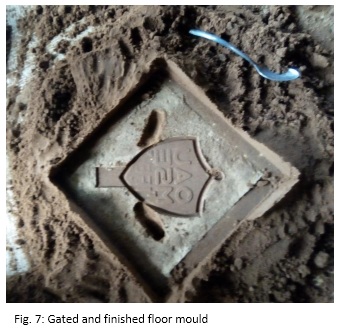
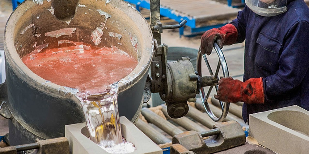
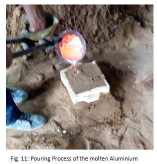
- With the cope and drag halves of the mould made, separate the cope from the drag, remove the pattern and re-aligne the two halves of the mould. And then, cut the sprue and other gating system for the completed mould; blow off loose sand from the mould and make sure the sprue hole was cut through and is clean. The mould should be properly re-aligned and the last step is pouring as shown below.
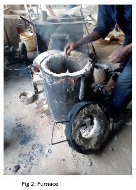
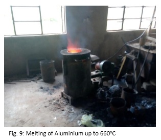
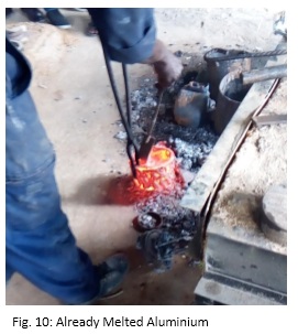
- The Aluminium should be melted at 660oC in the furnace
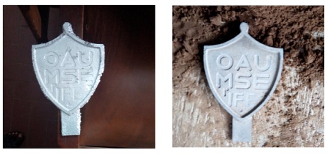
Data and Results
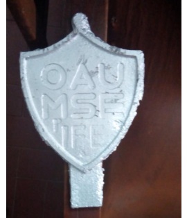
Comparing the Original Sample and the Melted Sample
Discussion of Results
- Observation:
As seen above, the casted product came out perfect except for little fettling process that must be carried out to perfecting the product. - Advantages of Casting Process:
- Molten metal flows into small ant section in the molten cavity. Hence any complex shape can be easily produced.
- Practically any material can be casted.
- Due to small cooling rate from all directions, the properties of casting are same in all directions.
- Any size of casting can be produced up to 200 tons
- Casting is the often cheapest and most direct way of producing a shape with certain desired mechanical properties.
- Certain metals and alloys such as highly creep resistant metal-based alloys for gas turbines cannot be worked mechanically and can be cast only.
- Heavy equipment like machine leads, ship’s propeller, etc. can be thrown easily in the required size rather than fabricating them by joining several small pieces.
- Casting is best suited for composite components requiring different properties in various direction. These are made by incorporating preferable inserts in a casting. For example, aluminum conductors into slots in iron armature for electric motors, wear resistant skins onto shock resistant components.
- Limitations of Casting Process:
- With normal sand casting process, the dimensional accuracies and surface finish is less.
- Defects are unavoidable.
- Sand casting is labor intensive.
Casting Defects, Causes and Prevention
- Gas hole
Gas hole is the hole that exists in the casting surface or internal area. It can be round, oval, or irregular shape, sometimes is an air mass made up of multiple gas holes.
Causes:- Preheating temperature of casting mould is too low, and cooling of liquid metal is too fast when it goes through the pouring system.
- The exhaust design of mould is not good, so that gas cannot flow out
- Bad coating material, poor exhaust, even volatile or break down the gas itself.
- Holes and pits are existed in the surface of mold cavity, when pouring liquid metal, the gas in the holes and pits are rapidly expanding, and compress gas liquid metal, thus to form choking hole.
- Surface of mold cavity is rust, and did not clean up.
Prevention Methods:- Mould should be fully preheat, the granularity of coatings (graphite) should not be too thin, and permeability needs to be good.
- Using tilt pouring way when casting.
- Raw materials should be stored in ventilated, dry place, and should be preheated when used.
- Pouring temperature should not be exorbitant.
- Shrinkage Cavity (Shrinkage
Shrinkage cavity is the surface rough hole in the casting surface or internal, slight shrinkage cavity is many scattered small shrinkage cavity, namely shrinkage. The grains of shrinkage cavity are big and thick. Often occur in the casting sprue, riser root, thick area, the connecting area between thin & wall thickness etc.
Causes:- Control of mold working temperature did not meet the requirements of directional solidification.
- Improper coating selection, the control of the coating layer thickness control in different areas is bad.
- The position of the investment casting part in the mold is not proper designed.
- Poured riser design did not meet fully the effect of feeding.
Prevention Methods:- Improve mold temperature
- Adjust the thickness of coating layer, even paint spraying, and avoid local coating accumulation phenomenon when coating paint falls off or filling.
- Local heating the mold, or local heat preservation using thermal insulation material.
- Design the heat sink in the mold, or the cooling speed accelerate the cooling speed in local area through water, or else spray water outside the mold.
- Place detachable handling chill blocks in turn inside the cavity, to avoid sufficient cooling of blocks when continuous production.
- Slag hole (flux slag or metal oxide slag)
Slag hole is clear or unclear hole in the casting. It is fully or partially filled by slag, and the shape is irregular. Small shape flux slag is not easy to be found, after removing slag, it will present smooth hole, general is distributed at the bottom area of the pouring position, around the inner section, or near the corner.
Causes:- Slag hole is mainly caused by alloy smelting process and pouring process (including improper design of gating system), the mold itself will not cause slag hole, and the metal mould is one of the effective methods to prevent slag inclusion.
Prevention Methods:- Correct gating system design, or use cast fiber filter.
- Using tilt pouring way.
- Choose the flux, and strictly control the quality.
- Crack (thermal crack, cold crack)
The appearance of the crack is linear or irregular curve. The surface of thermal crack is dark grey or black due to strong oxidation, no metallic luster. The fracture surface of cold crack is clean, with metallic luster. General casting crack can be seen directly, however, inside crack can only be seen using other methods. Cracks are often associated with defects such as shrinkage, slag inclusion. They are mostly occurred in the inside of casting angle, thickness of junction, and hot section between poured riser and castings.
Causes:- Metal mould casting is easy to produce crack defects, because the metal mould does not have deformability itself.
- High cooling speed will be easy to increase the casting internal stress. Too large or small pouring angle, too thin coating thickness etc. may all cause casting crack. Beside when there is a crack in the mold itself, it will also be easy to cause crack.
Prevention Methods:- Attention should be paid on the casting structure, make uniform transition of nonuniform wall thickness. And adopt the appropriate fillet size.
- Adjust the thickness of the coating, try to achieve the required cooling rate of each casting area, and avoid to form too large internal stress.
- The working temperature of the metal mould should be paid attention to and adjust the angle of mold.
- Cold Shut
Cold shut is a kind of slot or surface crack with round edge, the middle is separated by a scale, so it is not fully integrated. When the cold shot is serious, it will become “owe cast”. Cold shut often appears in the top wall of the casting, thin horizontal or vertical plane, or in the joint area of thin & thick wall thickness.
Causes:- The venting design of metal mold is not reasonable.
- Too low working temperature.
- Bad quality or improper operation of coating.
- Improper riser position design
- Pouring speed is too slow.
Prevention Methods:- Correct design the runner and exhaust system.
- Proper thicken the coating layer for thin wall thickness investment castings.
- Improve mold working temperature.
- Using tilt pouring way.
- Using mechanical vibration metal mould for casting.
- Sand hole
Sand hole is formed in the casting surface or internal, and is relatively regular. The shapes are consistent with the shape of the sand. When investment castings are taken out of the mold, we can see sand grains inlaid in the casting surface.
Causes:- Surface strength of sand core is not good, burning or not completely cured.
- The size of the sand core is not consistent with outer mold, or is crushed when clamping mold.
- The mould is polluted by graphite water and sand.
- The sand is rushed into the cavity.
Prevention Methods:- Making sand core according to the process distinctly.
- Keep the size of sand core consistent with outer mold.
- Timely clean graphite water.
- Clean the sand in mold cavity when putting sand core.
Conclusion
Sand casting should be used very often in metal production due to its many advantages. Though it has its own disadvantages, the advantages outweigh the disadvantages.


