Introduction
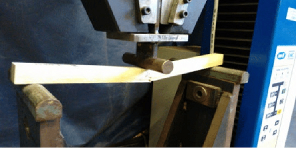
Bending test is an important test conducted on timber to determine the Modulus of Elasticity, E, and the Shear Modulus, G, of a given sample of wood using static bending.
Useful Terms
- Shear Force: The sum of all the forces acting perpendicular to the section or forces which tend to slides two part of the section on each other.
- Elastic Curve: A line representing the deformed form of the center line of the beam is known as Elastic Curve.
- Flexural Stress: Stresses produced by the bending moment is known as Flexural Stress.
- Stresses: Internal resistance of the material against loading is known as Stress.
- Flexural Equation: It is the fundamental relationship between the Bending moment and geometry of deformation

- Flexural Formula: It gives a relationship in bending moment and flexural stresses.

- Modulus of Rupture: it is the energy absorbed per unit volume when the specimen is loaded from zero to failure and it is the maximum tensile stress which can be developed in the beam before failure.
- Deflection: For a simply supported beam with central loading, deflection under the load is given by:

Where :
W= Applied Load
L = Effective span of the beam
E= Young’s Modulus of Wood
I = Moment of Inertia
d = Deflection under the load
Objective(s) of the Experiment
The test is carried out to study the bending or flexural behavior of the beam and to determine the Modulus of Elasticity and Modulus of Rupture of the wood.
Equipments and Materials Needed
The equipments and materials needed for bending test of wood include:
- 10 ton Buckton UTM
- Deflection Gauges
- Wooden Beam
- Measuring Tape
Procedures
Loading Arrangement for the Experiment
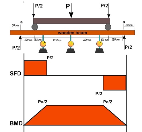
Loading arrangement for this certain experiment is “Two point Arrangement”. This is to produce only bending, it will not cause any shear force in the beam.
Two point Arrangement
Two equal loads acting at the equal distance from the supports is known as two point loading system. In such a system the shear force acting between the loads is zero and bending moment between the loads is constant as shown in the figure below.
- First of all measure the breath and height of the wooden sample using the measuring tape.
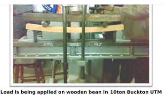
- Fix the wooden beam sample in 10 ton Buckton UTM.
- Adjust the support for the required distance and clamp to the lower table.
- Fix the traverse test pan at the lower side of the lower cross head. Fix it on the rollers of the traverse test brackets such that the loads comes at the centre and measure the length of the span of the beam between the supports for central loading.
- Adjust the load pointer to zero by lifting the lower table.
- Now apply the load gradually on the beam and note down the amount of deflection against each loading using the vernier scale on the UTM.
- Note down all the deflection up to failure of specimen and note the maximum deflection and the maximum load.
- Find the Modulus of Elasticity and Modulus of Rupture from their respective formulae. Check Below

Precautions
- Apply the loads gradually so that we can read the deflection against each reading easily.
- Remove the gauges before the failure load, otherwise they may get damages.
- Stay away from the machine for safety from the particles.
Results and Calculations
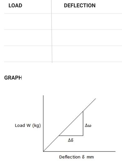
The graph of the Load against Deflection is plotted as shown below:
Range Calculation:
Extreme working stress in bending for wood = 15.2N/mm2
Factor of Safety (F.S) = 5
Thus, Ultimate Bending Stress, f-max = 15.2 x 5 = 76N/mm2
Modulus of Rupture, fmax:
From Bending Equation,

But Z= I/y ; thus, M = f x Z
For a simply supported beam with a concentrated load at the center, Maximum Bending Moment = WL/4, thus,

Where Fmax is the breaking load.
Young’s Modulus, E:
E = Stress/Strain

Take Dw/ Dd from the graph.
I = bh3/12; where b= breadth, h= height
Results
- Young’s Modulus of the material of wooden beam = _________
- Modulus of Rupture = ___________
References
- Chaudhary, A.J. “Bending Test on Wooden Beam”. http://www.scribd.com/
