Introduction
The California Bearing Ratio Test (CBR Test) is a penetration test developed by California State Highway Department (U.S.A.) before World War II for the evaluation of the natural ground, sub-grades and base-courses for design of flexible pavements or new carriageway constructions. It can also be used for measuring the load-bearing capacity of unimproved airstrips or for soils under paved airstrips.
The test is performed by measuring the pressure required to penetrate a soil sample with a plunger of standard area. The measured pressure is then divided by the pressure required to achieve an equal penetration on a standard crushed rock material. The CBR test is described in ASTM Standards D1883-05 (for laboratory-prepared samples) and D4429 (for soils in place in field), and AASHTO T193. The CBR test is fully described in BS 1377: Soils for civil engineering purposes: Part 4, Compaction related tests. It is the ratio of force per unit area required to penetrate a soil mass with standard circular piston at the rate of 1.25mm/min to that required for the corresponding penetration of a standard material.
Why is California Bearing Ratio Test Important?
CBR test is essentially a test for bearing capacity of ground under an application of load at a low rate of penetration. In actual pavement, it is the dynamic stiffness of pavement which is of paramount importance because the pavement is subjected to repeated loading at low stress levels. Design procedures based on dynamic stiffness can be adopted but difficulties are encountered in selecting appropriate modulus for dynamic stiffness. It sounds complicated, but the basis behind it is quite simple. We are determining the resistance of the sub-grade, (i.e. the layer of naturally occurring material upon which the road is built), to deformation under the load from vehicle wheels. Even more simply put, ''How strong is the ground upon which we are going to build the road''. The stronger the sub-grade (the higher the CBR reading) the less thick it is necessary to design and construct the road pavement, this gives a considerable cost saving. Conversely, if CBR testing indicates the sub-grade is weak (a low CBR reading) we must construct a suitable thicker road pavement to spread the wheel load over a greater area of the weak sub-grade in order that the weak sub-grade material is not deformed, causing the road pavement to fail.
Objective(s) of the Experiment
This practical is carried out to assess the bearing capacity of materials for sub-grades, sub-bases, and base courses for design of flexible pavements.
Equipments and Materials Needed
- Cylindrical mould with inside diameter 150mm and height 175mm, provided with a detachable extension collar 50mm height and a detachable perforated base plate 10mm thick.
- Spacer disc 148mm in diameter and 47.7mm in height along with handle
- Metal rammers: Weight 2.5kg with a drop 310mm or weight 4.5kg with drop of 450mm.
- Weights: one annular metal weight and several slotted weights weighing 2.5kg each, 147mm in diameter with a central hole of 53mm diameter.
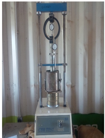
- Loading machine with a capacity of at least 5000kg and equipped with a movable head or base that travels at a uniform rate of 1.25mm/min, complete with a load indicating device.
- Metal penetration piston of 50mm diameter and minimum of 100mm in length.
- Two dual gauges reading to 0.01mm.
- Miscellaneous apparatus, such as straight edge, scale, paper and containers
Procedures
- Take about 5 - 6kg of soil and mix thoroughly with the required water.
- Fix the extension collar and base plate to the mould. Place the filter paper on top of the base plate and weigh the arrangement.
- Compact the mould using either light compaction or heavy compaction. For light compaction, compact the soil in 3 equal layers, each layer being given 62 blows by the 2.5kg rammer. For heavy compaction, compact the soil in 5 layers, 62 blows to each layer by the 4.5kg rammer.
- Remove the collar and trim off the soil.
- Record the weight of the mould and the contained soil.
- Put the filter paper on top of the compacted soil and clamp the perforated base plate on to it.
- Put annular weights to produce a surcharge equal to weight of base material and pavement expected in actual construction. Each 2.5kg weight is equivalent to 7cm construction. A minimum of two weights should be put.
- Place the mould assembly with the surcharge weights on the penetration machine.
- Seat the penetration piston at the center of the specimen with the smallest possible load, but in no case in excess of 4kg so that full contact of the piston on the sample is established.
- Set the stress and strain gauges to zero, and apply the load on the piston so that the penetration rate is about 1.25mm/min.
- Record the load readings at penetration of 0.25, 0.5, 0.75,…,2.25, 2.5mm. That is at 0.25mm interval. Then record the load bearing at penetration of 3.0, 3.5, 4.0, 4.5, and 5.0mm. That is at 0.5mm interval.
- Detach the mould from the loading equipment, remove the base plate and re-fix the mould on it with the mould now facing down.
- Repeat procedures (6) – (11).

Results and Calculations
The following steps are followed in calculating the CBR value:
- The readings (in div) for 2.5mm and 5.0mm penetration for both top and bottom surface of the mould is recorded.
- Multiply the readings by the ‘Ring Load’ of the machine (For example, for the CBR machine of the type shown above, the ring load is 0.052kN/div). This gives the forces on the plunger.
- Divide the forces on the plunger for the 2.5mm penetrations by 13.24 and multiply the result by 100. This gives the CBR at 2.5mm penetration. Record as follows:
- CBR of specimen at 2.5mm penetration (top) = _______%
- CBR of specimen at 2.5mm penetration (bottom) = _______%
- Similarly, divide the forces on the plunger for the 5.0mm penetrations by 19.96 and multiply the result by 100. This gives the CBR at 5.0mm penetration. Record as follows:
- CBR of specimen at 5.0mm penetration (top) = _______%
- CBR of specimen at 5.0mm penetration (bottom) = _______%
- The bearing value is the average of the four CBR values (in percentage).
.
An example of the calculation is shown in the figure below:

Discussion and Conclusion
- CBR test may be conducted in the laboratory either on remoulded or undisturbed soil specimens. CBR test can also be conducted in the field.
- CBR test is done both on the soaked and unsoaked samples. Soaking of specimen simulate the worst field condition that a subgrade soil can be subjected to, similar to monsoon and post-monsoon conditions.

References
- “CBR TEST OF SOIL-10+ MOST IMPORTANT NOTES TO REMEMBER” www.civilblog.org. June, 2014.
Credits: Samuel Alalade. Obafemi Awolowo University, Ile-Ife, Osun State, Nigeria.
